ranchhelper
-
Posts
41 -
Joined
-
Last visited
Content Type
Profiles
Forum
Gallery
ATV Magazine
Events Calendar
Downloads
Store
Community Map
Everything posted by ranchhelper
-
225cc airbox. I found one (for a lot more) but it's for a 350. Idk if they use the same airbox, but probably not. https://www.ebay.com/itm/403997392440 Possibly closer. What do you think? You can delete everything starting with ?mckid, it's all tracking cookie info.
-
Want to thank @Gwbarmand @Mech Next will be carb and then oil filter/oil change, and whatever other fluids (rear diff). A battery, a new relay, getting ehe lights reconnected. Edit: the airbox and filter is completely missing. If anyone has tips on that. Not that I want to spend the money, but will this fit? Air Box Filter Box Cleaner Case With Lid Cap For YAMAHA Warrior 350 Grizzly 600 1987-2004 Wolverine 350 1995-2005 https://a.co/d/aAPHLP2
-
Ok, I don't have a video to post yet because I made a progress / question / frustration video then, in getting that out, ah freedom of speech *pause* talking about the PO etc. The realization occured, that - if you look at my prior video you'll see it: there are two engine start/stop controls. The original Yamaha one, and one taken off a later model motorcycle or ATV, mounted on the same side of the handlebar, adjacent. It's that second one which runs underneath the tank, and did not have any matching color codes, nor was it connected to the harness. That's the one they cut into, and added crazy ROMEX to instead of proper low voltage stranded wire, then used it's START push switch, to directly electrically bridge the terminals on the starter relay (solenoid), completely bypassing the function of the solenoid, and only using it's terminals exclusively as you would use 2 isolation lugs. Like shoving a screwdriver across them every time you start the engine. The CDI is on the forward-facing side of the battery tray, in the back, near the left-rear tire, and just underneath the CDI is where the starter solenoid is supposed to go. That's those blue and black wires from the harness, that do have a connector, that connects to a mating connector terminating in stripped wires. The new start solenoid will have it's own pigtail that will plug right into the existing harness. I'll have to look around for the retainer strap to hold the solenoid on. The tabs are there. I completely tested, then disassembled the original START - STOP - HEADLIGHT assembly. The START button did not work. Somewhere in the wires before the harness, the two brown wires are combined. So if you run a continuity probe between the brown on the 4-pin terminal to the red w/white on the 3-pin, and push START, you should get continuity if the START button works. Gently disassemble everything, and on the START button, use a dental pick to get underneath the bottom of the white switch body, and then you should be able to depress the START button and it will shift back then free. Feed yourself some of the cable through the grommet. This will give you room to disassemble the START switch and clean the contacts. Cleaning the contacts provides some conductivity, but the travel was too far and the connection was so-so. Use a 50-watt soldering iron and silver doped solder, and non-corrosive flux, flux the button on the back tab of the START button contact. Apply a little solder to your iron, then touch the button briefly until you have a nice round bead covering the whole face of the contact. Use a fine file and flatten the surface down some to around 1/2mm. You need to do this because too much of a nice round projection of solder, will not give enough travel for the button. Reassemble. The START button now works every time, and travel is about half of what it was. Properly assembled, current across the START button contacts should only be enough to fire a small relay, the starter solenoid. While you have the switch assembly apart, add silicone grease to the light switch contacts and mechanism, and the ENGINE STOP slide switch. I've completely removed the second START switch assembly, but may reuse it at a later time for a horn. Unless someone knows of an ATV turn signal kit they'd recommend, the switch to mount to the handlebar.
-
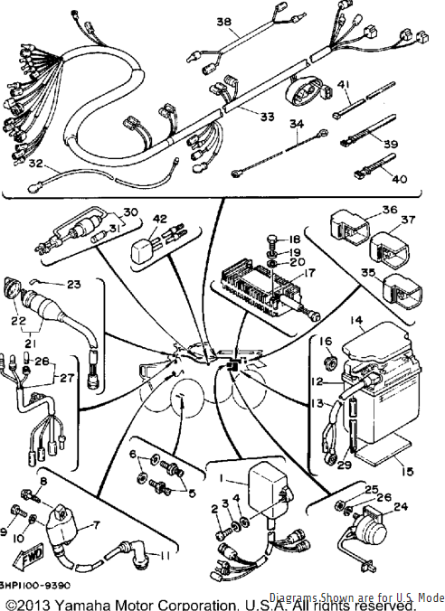
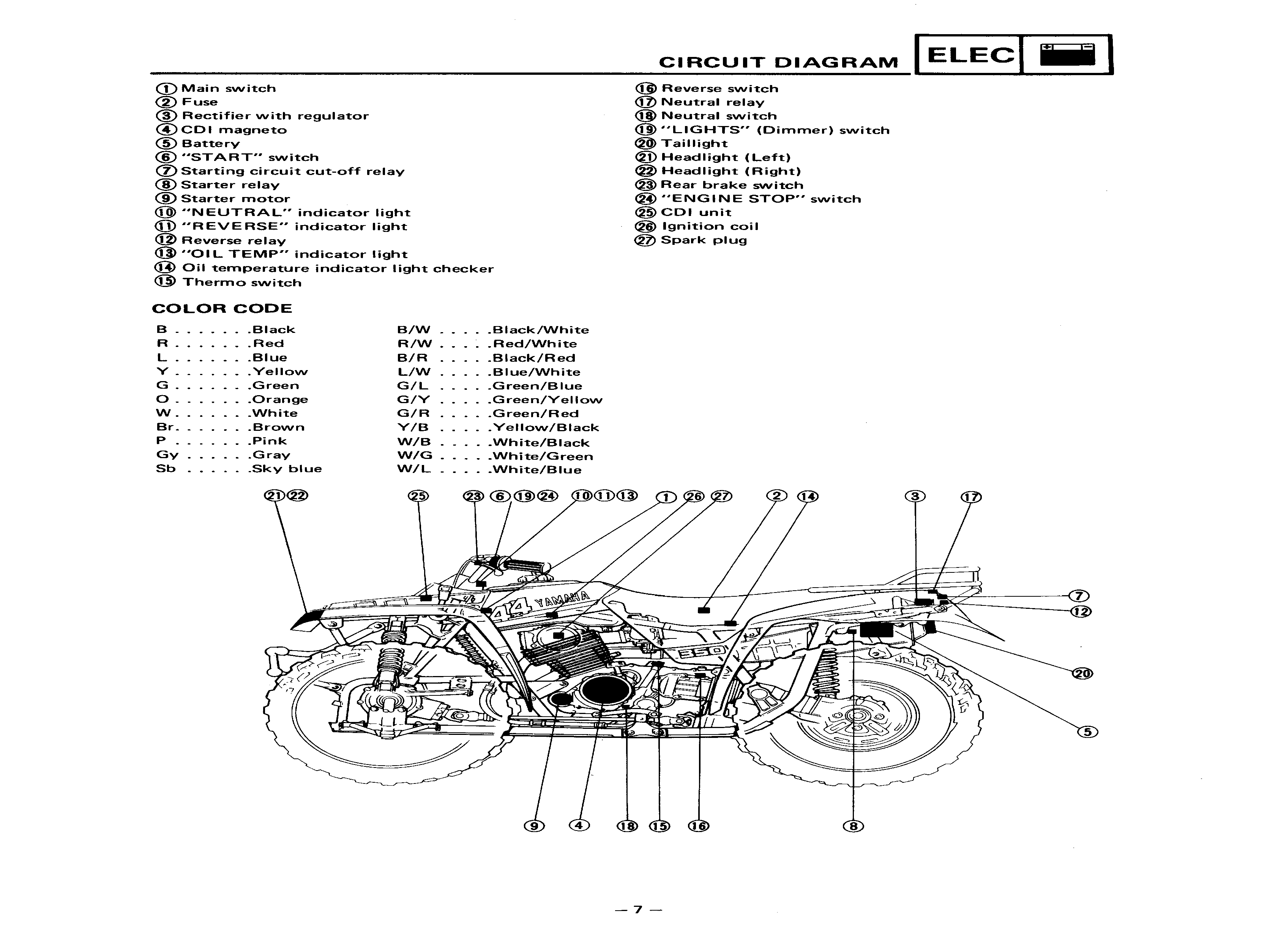
1 Cdi Unit Assembly 3HN-85540-00-00 2 Screw, Pan Head 98580-06020-00 $5.59 2 3 Washer, Spring 92995-06100-00 $2.95 2 4 .Washer, Plate 92990-06600-00 $2.95 2 5 Reverse Switch Assembly 24W-82540-00-00 4GY-82540-10-00 $27.19 2 6 .Gasket 90430-10171-00 $2.95 2 7 Ignition Coil Assembly 1UY-82310-41-00 $130.39 1 8 Bolt 90109-06723-00 $5.59 1 9 Bolt 97011-06020-00 97017-06020-00 $2.95 1 10 Washer, Spring 92995-06100-00 $2.95 1 11 Plug Cap Assy 1UY-82370-20-00 3NS-82370-00-00 $27.19 1 12 Battery BTG-GM14A-Z4-A0 CB1-4A200-00-00 13 Wire, Plus Lead 1YW-82115-00-00 $35.19 1 14 Cover, Battery 24W-82129-00-00 15 Damper, Locating 3 5X2-24183-00-00 5Y1-82122-00-00 $5.59 1 16 Pad, Battery 371-82121-00-00 $6.39 3 17 Rectifier/Reg Assembly 1YW-81960-A0-00 18 Bolt, Hexagon 97313-06016-00 97D95-06016-00 $2.95 2 19 Washer, Spring 92995-06100-00 $2.95 2 20 Washer 92901-06600-00 92990-06600-00 $2.95 2 21 Main Switch Assembly 2FJ-82510-02-00 2FJ-82510-09-00 $68.79 1 22 . Cap, Key 24W-82579-00-00 $23.19 1 23 Label 29U-83585-10-00 24 Starter Relay Assy (Ms5d-611) 4KD-81940-00-00 $83.99 1 25 Nut 95380-06700-00 $5.59 2 26 Washer, Spring 92995-06100-00 $2.95 2 27 Pilot Light Assembly 2HT-83530-00-00 28 . Bulb, Meter 12V 3.4W 4G1-84744-00-00 4G1-84744-00-XX 29 Hose (L540) 90445-082F3-00 90445-084J0-00 $13.59 1 30 Fuse Holder Assembly 59V-82150-00-00 2NL-82150-00-00 31 . .Fuse (30A) 705-82151-00-00 705-82151-01-00 $3.84 2 32 Wire, Lead 2JX-82541-00-00 33 Wire Harness Assembly 2VA-82590-10-00 34 Wire, Lead 1YW-82507-00-00 35 Relay Assembly 1UY-81950-91-00 1UY-81950-92-00 $54.39 1 36 Relay Assy (Aca12115-1) 29U-81950-93-00 $55.99 1 37 Relay Assy (Aca12115-1) 29U-81950-93-00 $55.99 1 38 Wire, Lead 59V-82541-00-00 39 Band, Switch Cord 437-83936-01-00 $5.59 4 40 Band, Switch Cord 437-83936-11-00 $3.19 3 41 Clamp 90464-14117-00 90464-15152-00 $3.99 1 42 Checker, Pilot Lamp 38W-85774-00-00 https://www.babbittsonline.com/oemparts/a/yam/50038943f870021f60a0a02f/electrical-1#

-
@Mech There are several links to pay sites which claim to have the 1987-1990 YFM350ER service manual, and the price varies from $10 to $25+. No way to tell if that's really it, or what kind of guarantee if it isn't what they say it is. I don't have more money right now because I spent what I had to get the ATV.
-
Does anyone (like a CLYMER etc) have a practical layout guide for the harness? As if you had no other vehicles to look at, and someone gave you a harness, and the vehicle, where would it go? How would it route? I kinda agree with @Gwbarm but am having trouble finding something that shows practical wire routing.
-
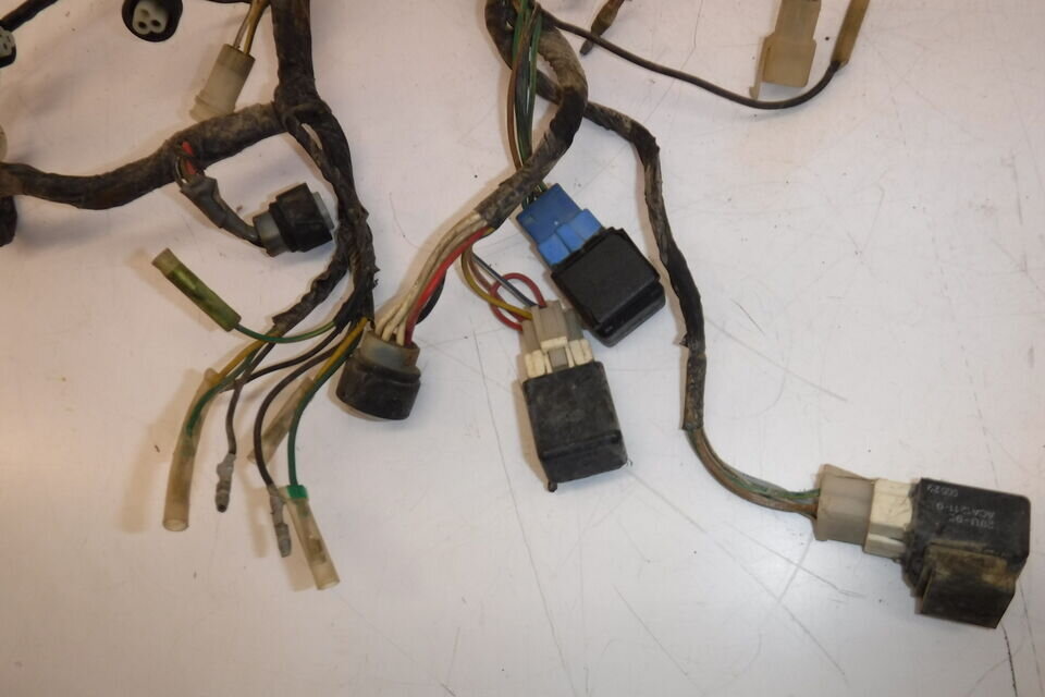
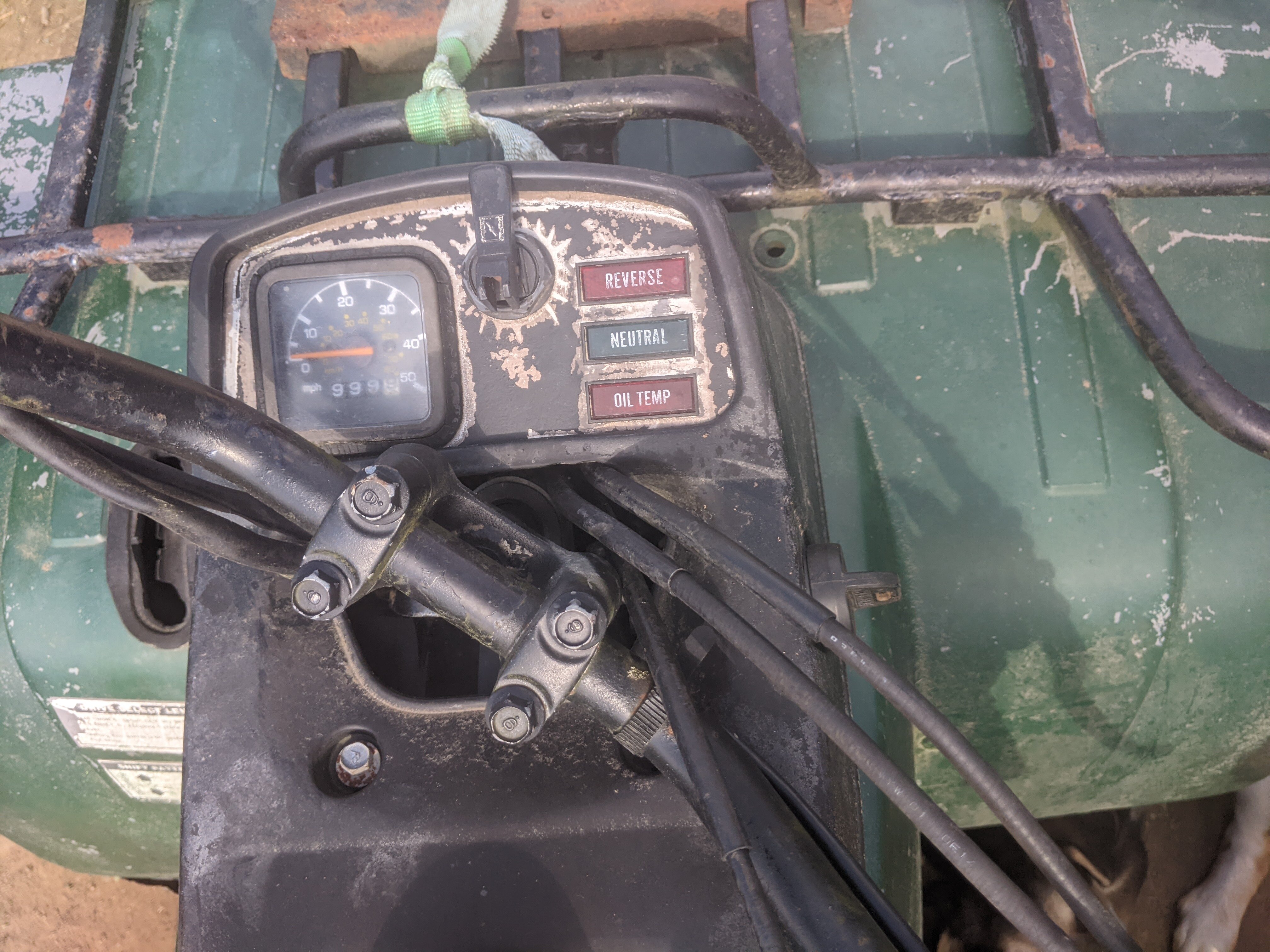
The 3-pin and 4-pin plugs go into what I thought was the main harness. But following them around, they all go directly to the START switch, engine stop, and mystery switch above those in the video below: The 3-pin goes to start/stop. The 4-pin goes to a black slide switch above those that is unlabelled. I'm sure any owner is going to know what that switch is for, and I'll watch that 1988 video @Gwbarm posted now.
-
@GwbarmIf I can get a member who has a 1989-90, to tell me what goes into the 3-pin and the 4-pin connector, just under the left side of the tank, then I can fix up the rest well enough to do as you say, the engine etc. It feels and looks solid. Just janky electric is my guess at this point.
-
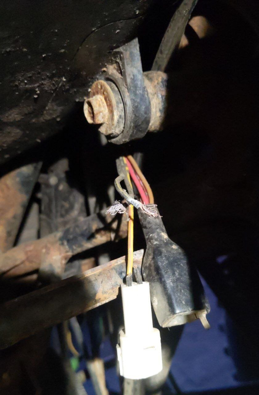
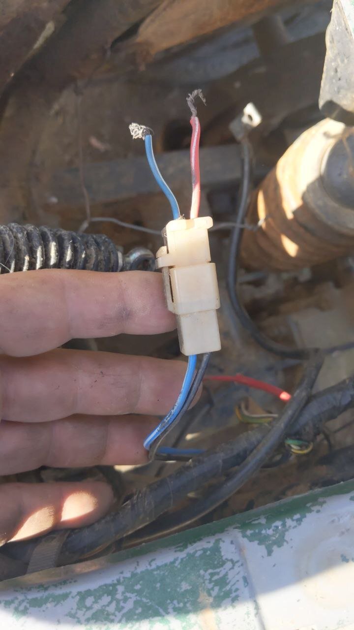
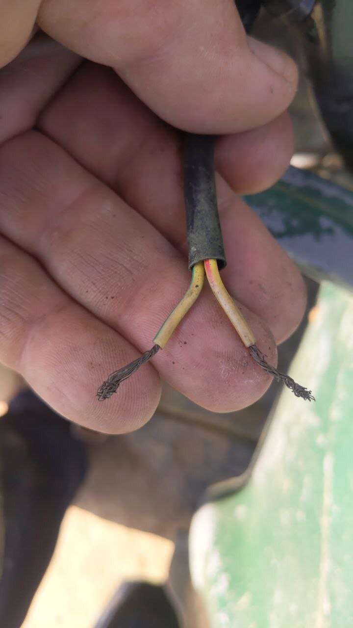
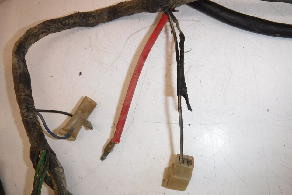
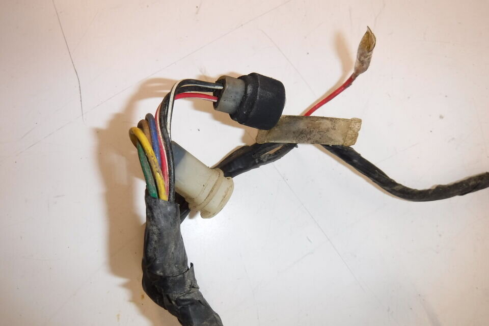
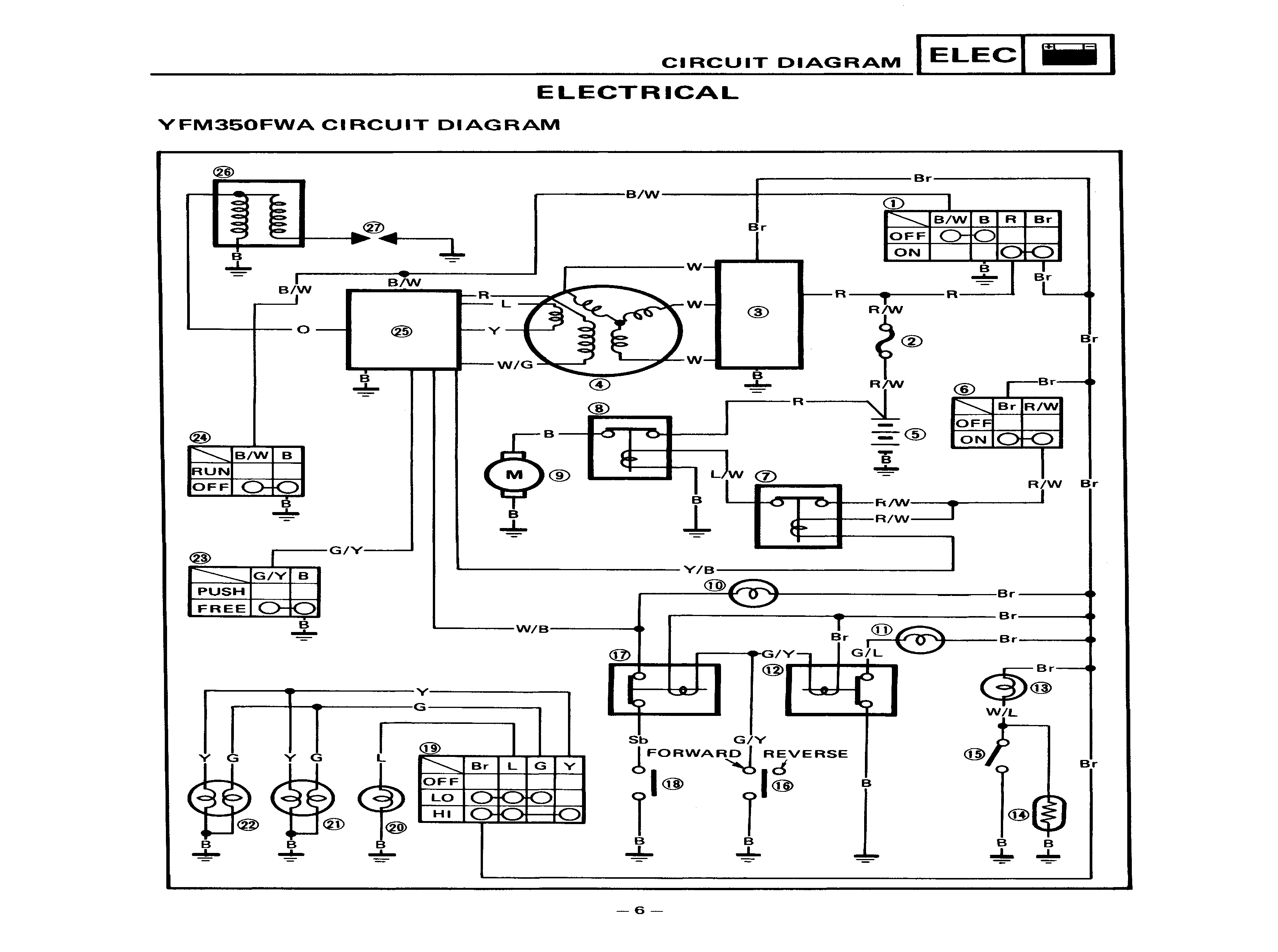
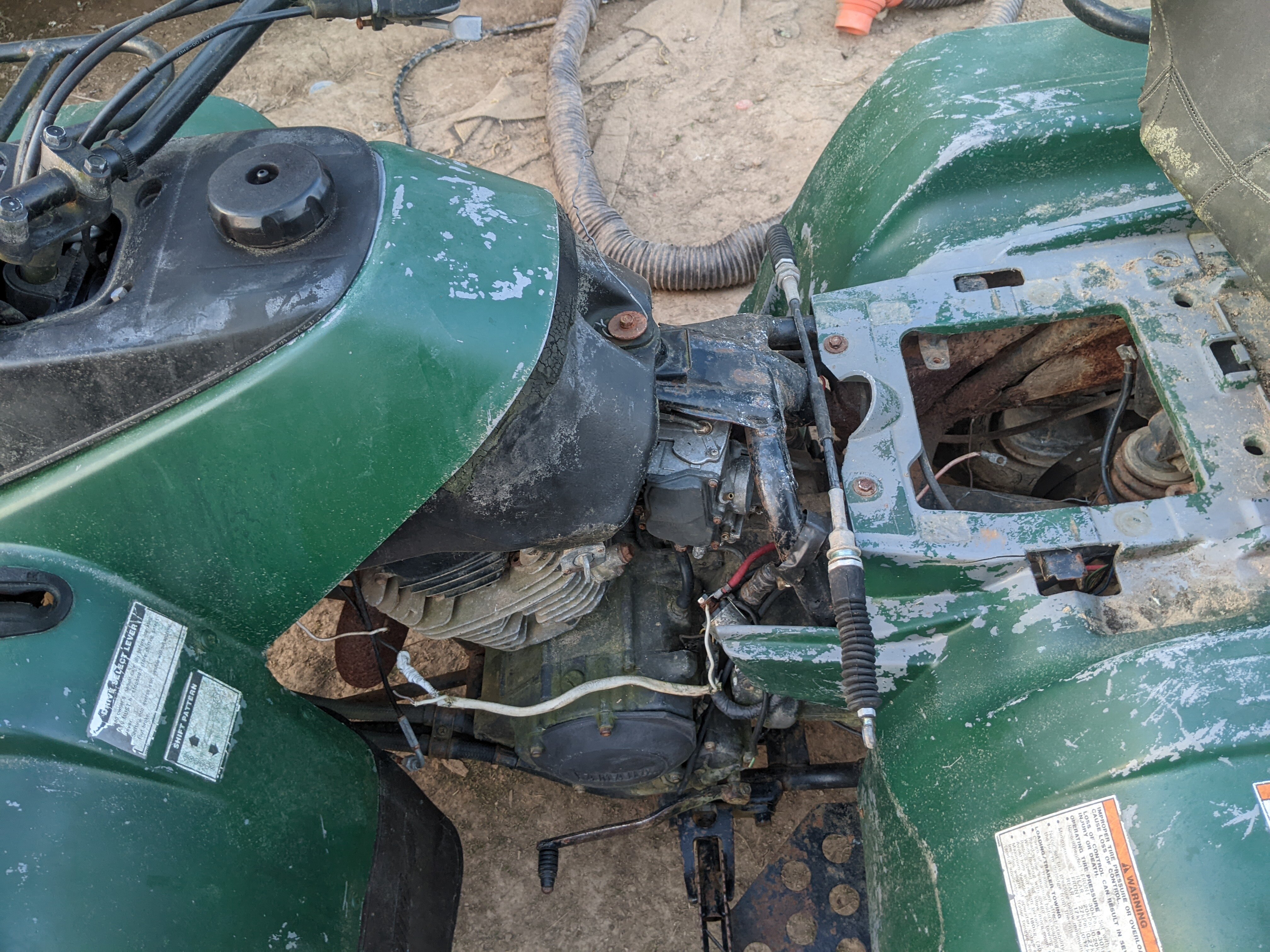
@Mech that is very helpful information! There is a post you probably have not seen yet, as it is awaiting approval. Here is a photo of the forward mystery wiring. This is just underneath the left side of the gas tank, extending down. Two wires were cut from the back of the 3-pin coming off the harness, and 'hot wired' -nutted- to the romex, with black going to one main terminal on the solenoid, and white going to the other. The same terminals had both the heavy red wire and heavy black wires connecting to them. Don't ask me what the prior was trying to do. Here's the notes about the wire color codes: I looked at both the 87 and 90 wiring diagrams, and neither have a 3 pin and 4 pin connector that correspond to these. That's why an actual pragmatic layout wiring diagram would be useful, to show actual people what goes where... oh but then insecure designers would be afraid of being less needed. I guess.. These colors are as accurate as I could determine. There may have been some color fading. Where I put multiple options, it was not clear. White 3-pin connector: Yellow w red stripe Black w green? Yellow? black Black 4-pin: Red Red w yellow stripe red w black stripe brown
-
I found a standard $10 starter solenoid. With the connector meant for the YFM350 (amazon). I looked around for an exhaust and the best i can seem to do is $160. Since it seems to have a standard sized pipe past the heat-shield, is there another more generic exhaust for a 350cc engine? Carbs... carbs all over for $40 new. Any suggestions? Apparently, Walmart sells the Valvoline ATV motor oil for wet clutches. Or Rotella T 15-40w is supposed to work. Suggestions? Any opinions on those NOCO batteries? The black lithiums. Or what do you suggest? I can stick a small solar panel on the back, with a built-in regulator, to keep a lead-acid charged. This is going to be really loud with that rust hole jn the exhaust.. can't wait.
-
-
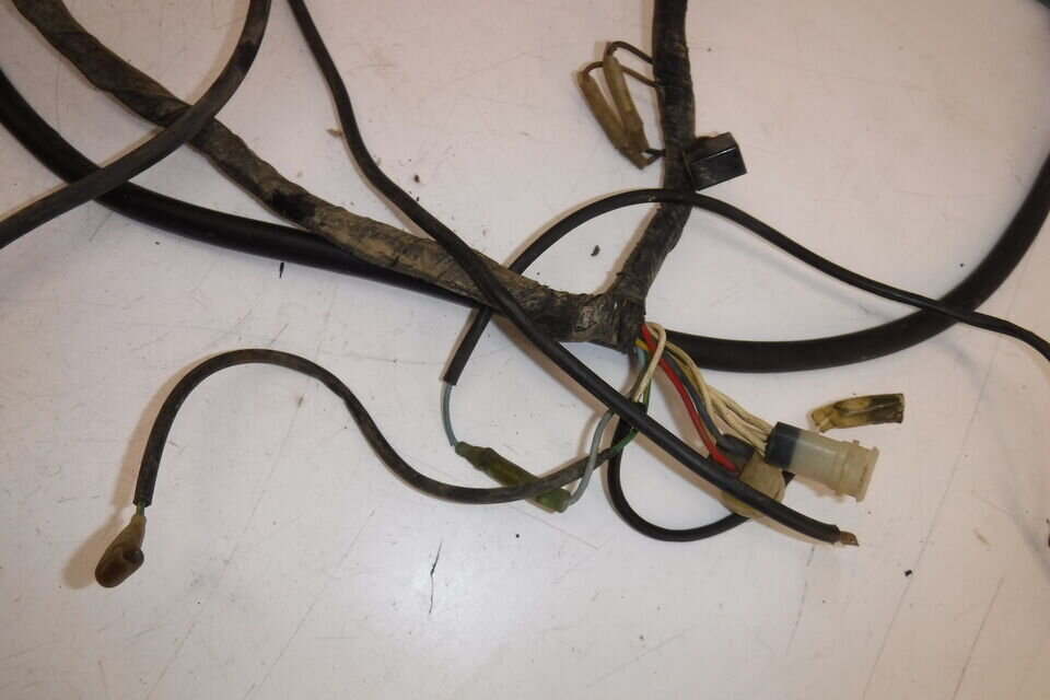
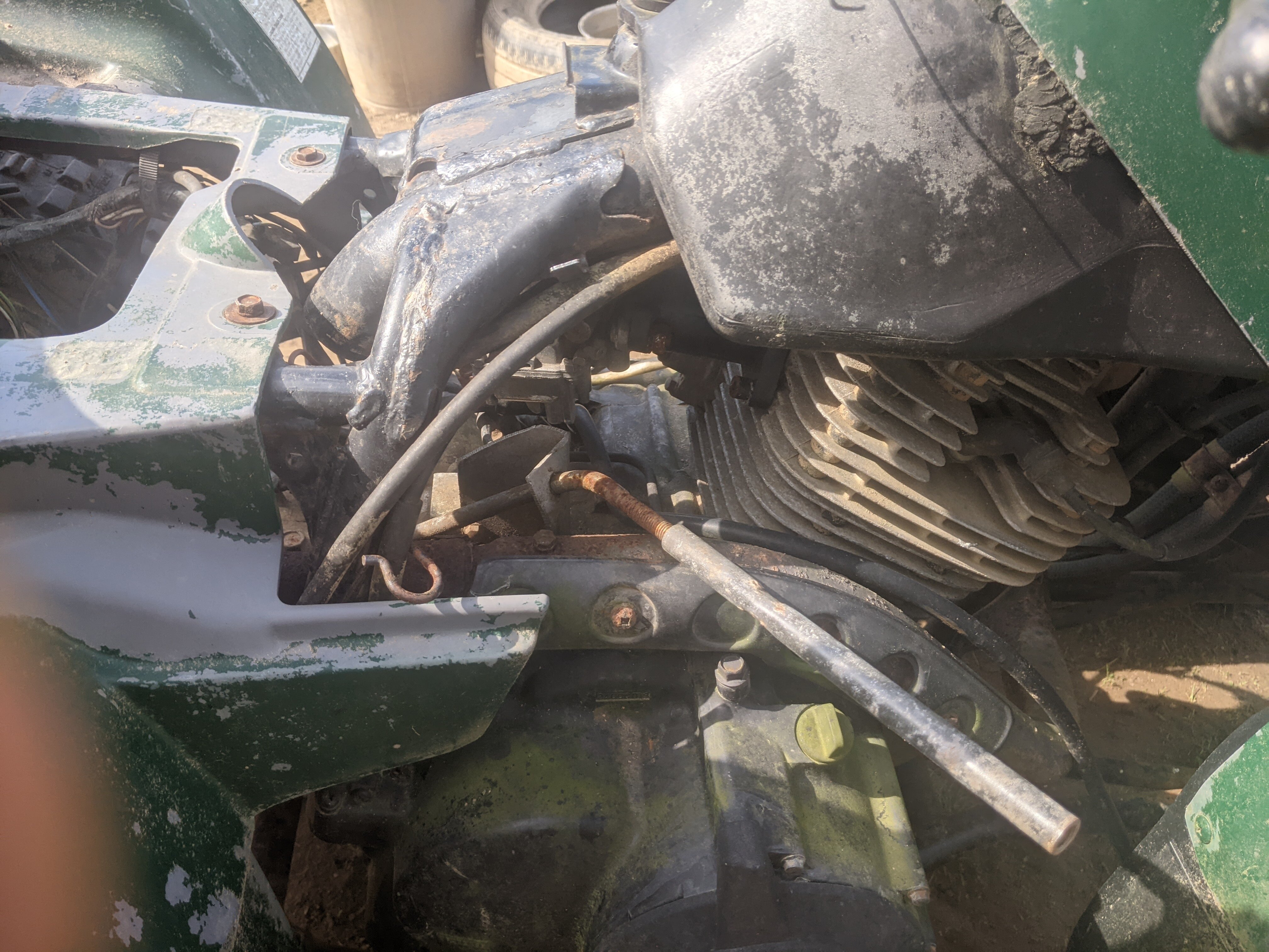
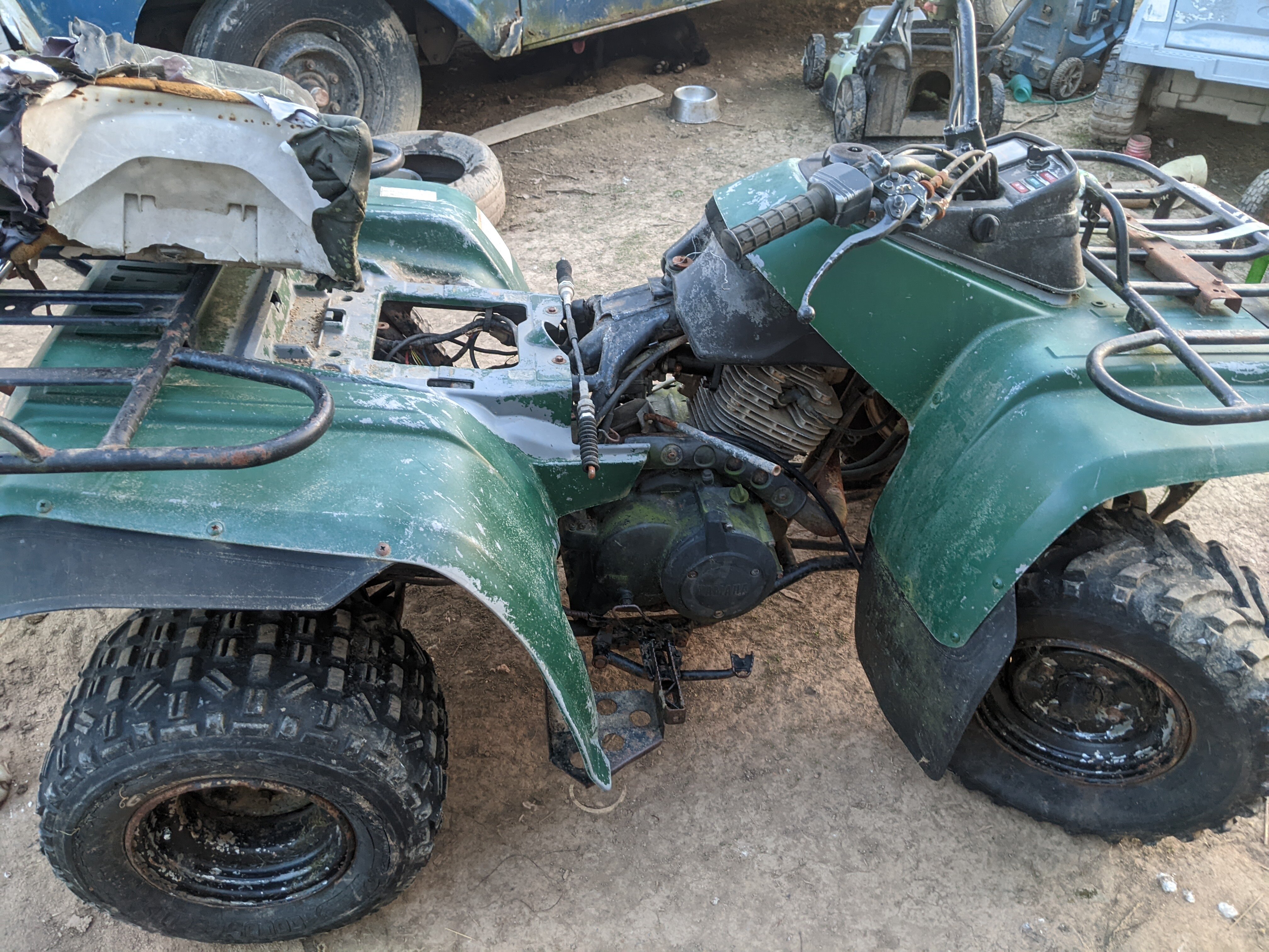
@MechThank you. It's 'ranch' like the dressing, my bad. I asked admin to change it and add the 'A' so it's easier to read. Of the two mystery wire issues, one in the front under the tank and one in the rear under the seat, the rear has a black & blue w/white stripe wire coming from the loom underneath the seat near the battery and near where the starting solenoid should be, and there's a connector with a red w/white & blue w/white wire connected to it, in the video. The wire then just terminates in stripped wire, like the connector was cut-off something (original solenoid). Then, the solenoid that is there, has got what looks like a white w/green and a white w/red wire, coming out as control wires (to fire the solenoid), but not connected to anything at all, again just dangling in air. So here's what I propose as a theory: the starter solenoid failed on the previous owner, then a very bad attempt was made at rewiring it. Looking at the 1990 - and 1987; there is no '88 or '89 - wiring diagram from the above PDF, the control wires for the solenoid would be from the harness, black & blue w/white, going into a connector with red w/white & blue w/white wires. So some other year/make/model of bike/ATV had a solenoid that had a white w/green stripe & white w/red stripe control wire, and they swapped the other solenoid in as a replacement. Feel free to post a link to a suggested replacement solenoid. That one on it now, might work, but it looks sketch, and I'd prefer to start over fresh with whatever is the best, without going overboard. Then I'll strip out their weird wiring repair stuff and try to figure out what those connectors are upfront in the video that seem to be wire-nutted into that romex, where those two connectors aren't connected to anything. Accuse me of being lazy, but to pull off that stator cover and try to fix-up those wires that go into the stator/generator, where the outer jacket is missing, to protect the individual conductors, do I need to drain the oil? I'm going to do that anyway, drain the oil and check some other things before trying to fire it up. I assume that cover is a dry cover... It's been ages since I worked on motorbikes. Oil brand suggestions etc would be welcome. I normally use Mobile 1 0-40 syn on everything, but I understand with the integrated clutch that motorcycle engines are different. I don't remember all the details.
-
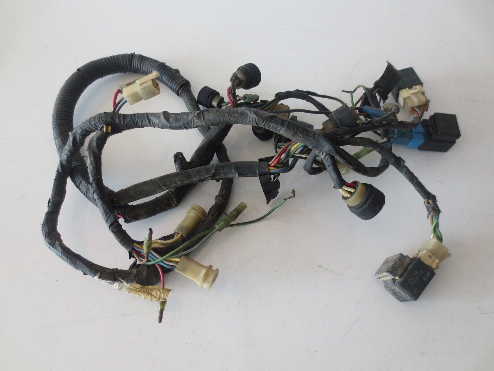
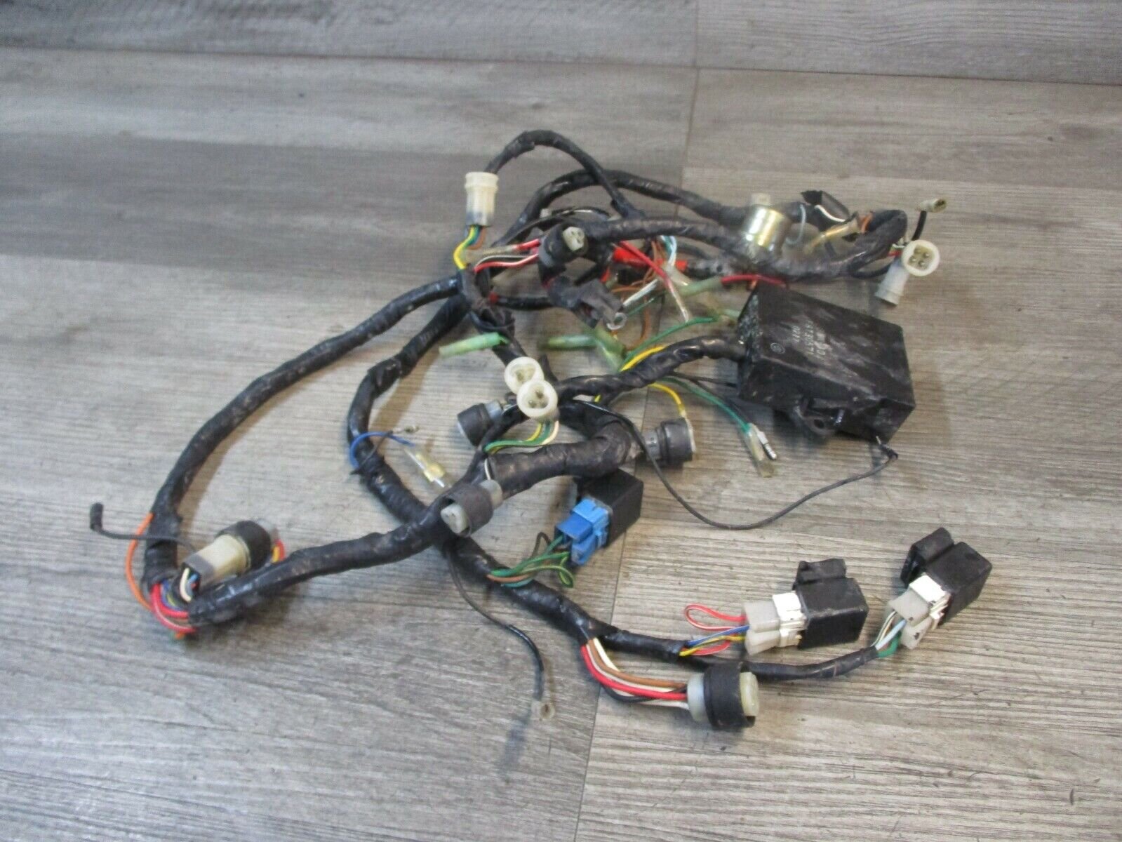
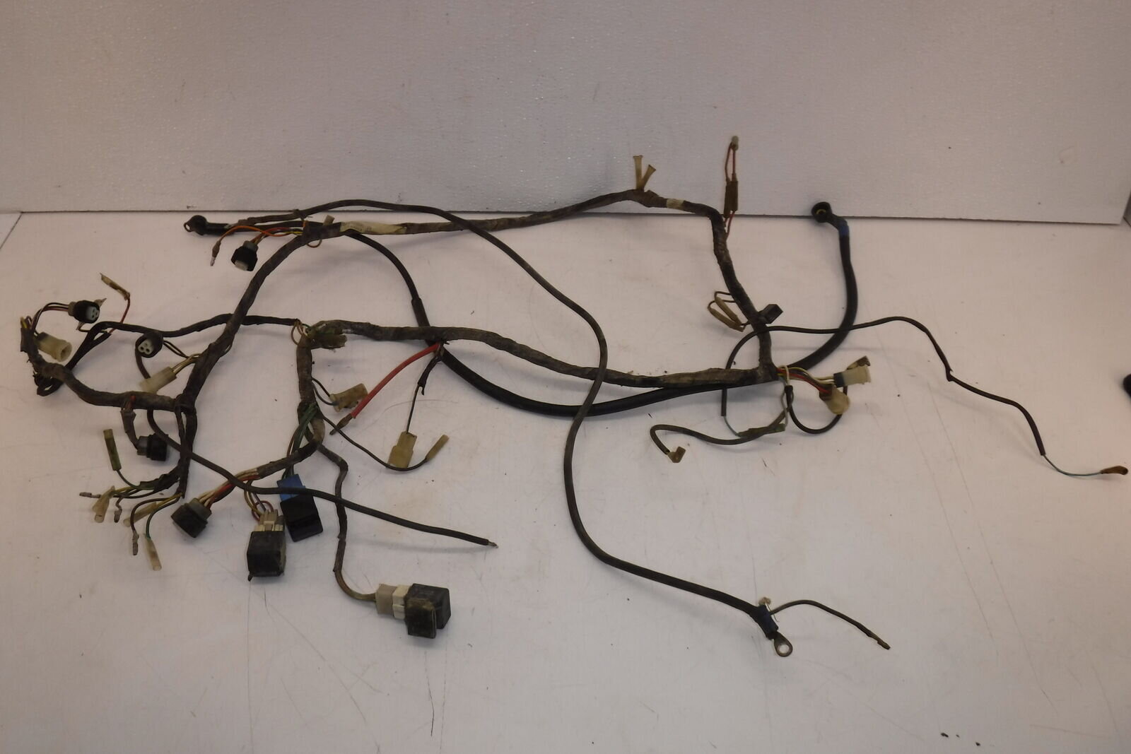
@Gwbarm2 wheel drive. Fine by me, less to fail/fix. Further inspection of electrical: It seems the harness is in decent shape, with the exception of whatever happened with the solenoid. So I can keep it, but there are some parts that need to be sorted-out. If either of you have a similar model, I would like to see what your layout looks like in a video. Just shot this with the Telegram app, saved to gallery, and uploaded to youtube as an unlisted video.
-
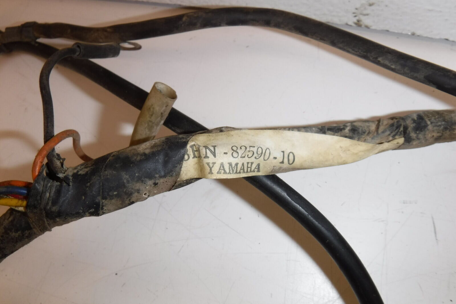
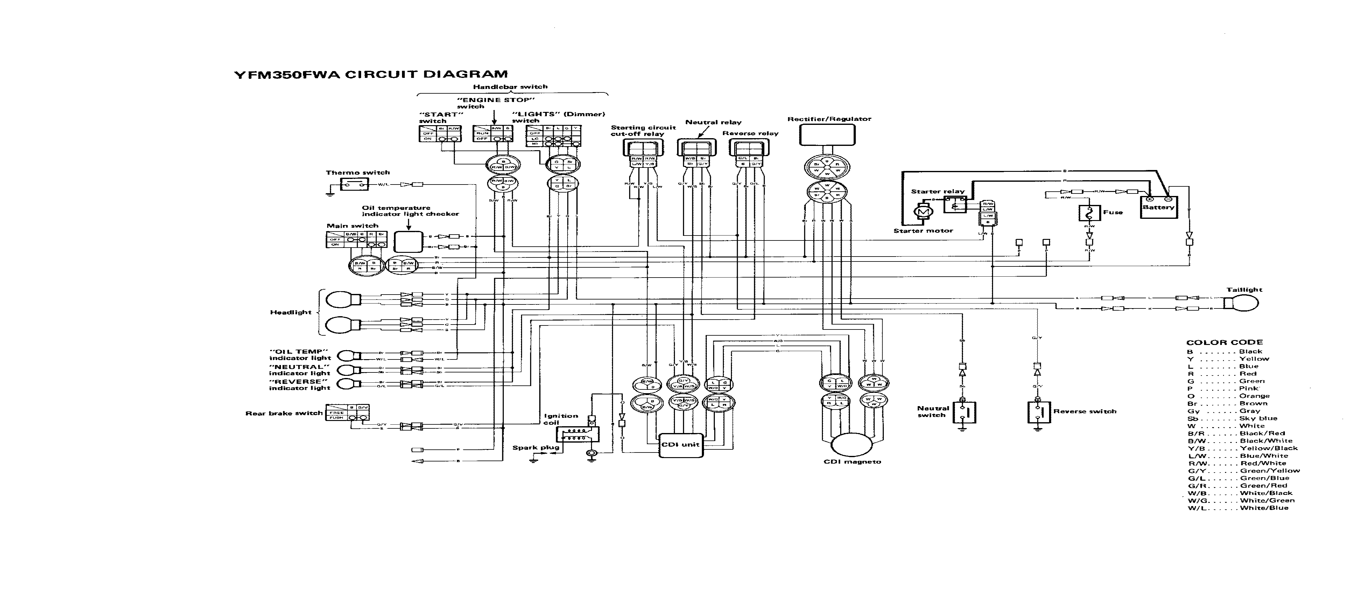
Here are some available wiring harnesses on ebay. They want a lot of money for them. Here is pages 348-350 of the 1987-1997-yamaha-big-bear-350-service-manual.pdf, both as a PDF and PNG image files. Here is an Amazon offer of a wiring harness from the same year of a YFM350X Warrior https://www.amazon.com/Caltric-compatible-Complete-Harness-1992-1995/dp/B09JC8YZ5J/ Despite the link saying 1992-1995, the text says "Caltric Complete Wire Harness Compatible with Yamaha Warrior 350 YFM350X 1990 1991 1992-1995 Wiring Harness" @Mech Whether it's a 1989 or 90, that harness should work, no? I'm thinking you and several other people like @Gwbarm can have an eyeball at these, and figure out if that Warrior harness at ~$35 would work sufficiently. I included the ebay images for completeness; and you know, someone else may need this post in the future. Not because I can afford to buy them (I can't). There are several other Amazon offers for wiring harnesses https://www.amazon.com/dp/B0BVVY5W4S and I'm wondering if they are all that different, or can be modified to work. Part number from that babbit website: 2VA-82590-10-00 Video of the electrical system: Pages 348-350 from 1987-1997-yamaha-big-bear-350-service-manual.pdf
-
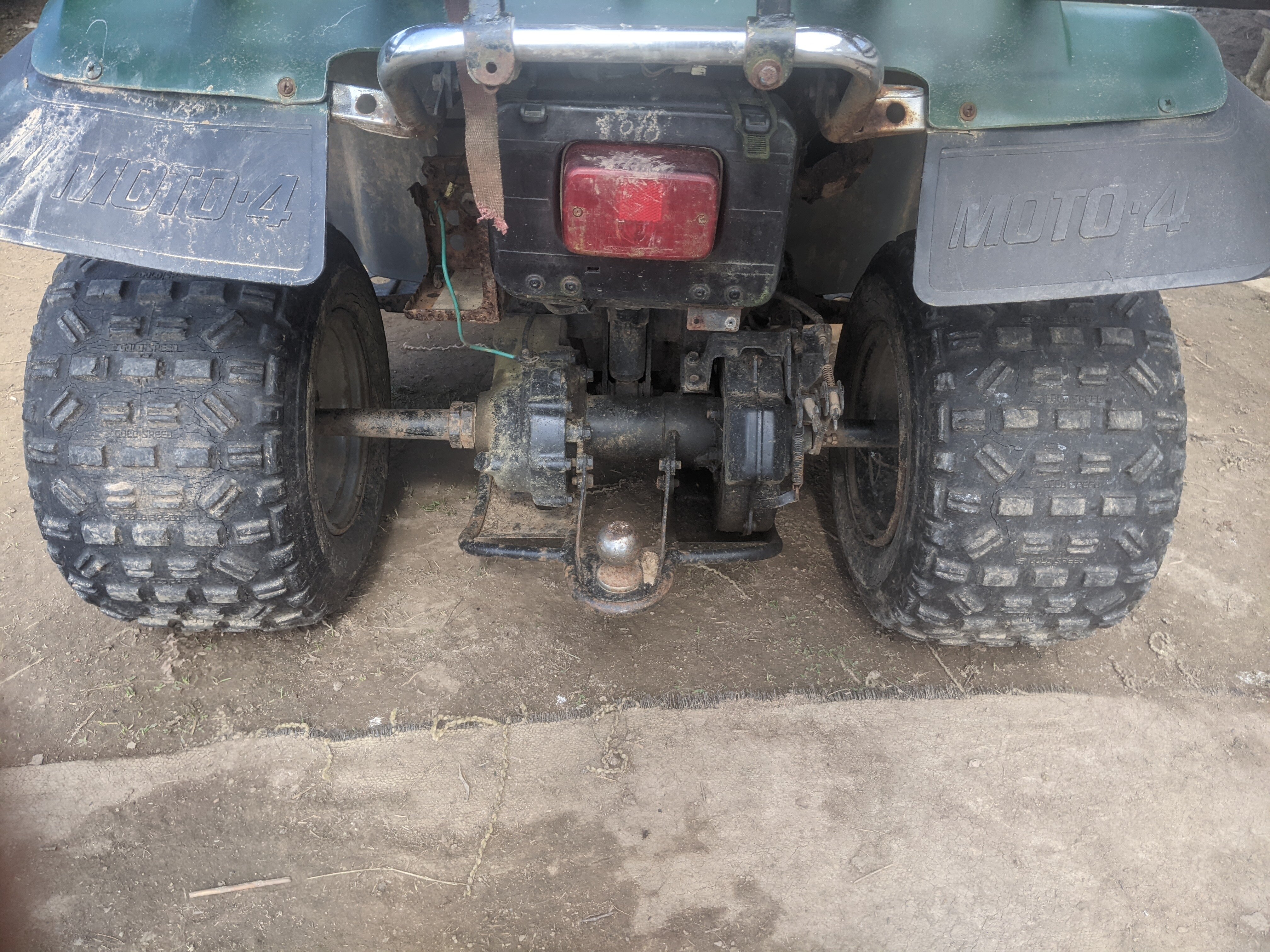
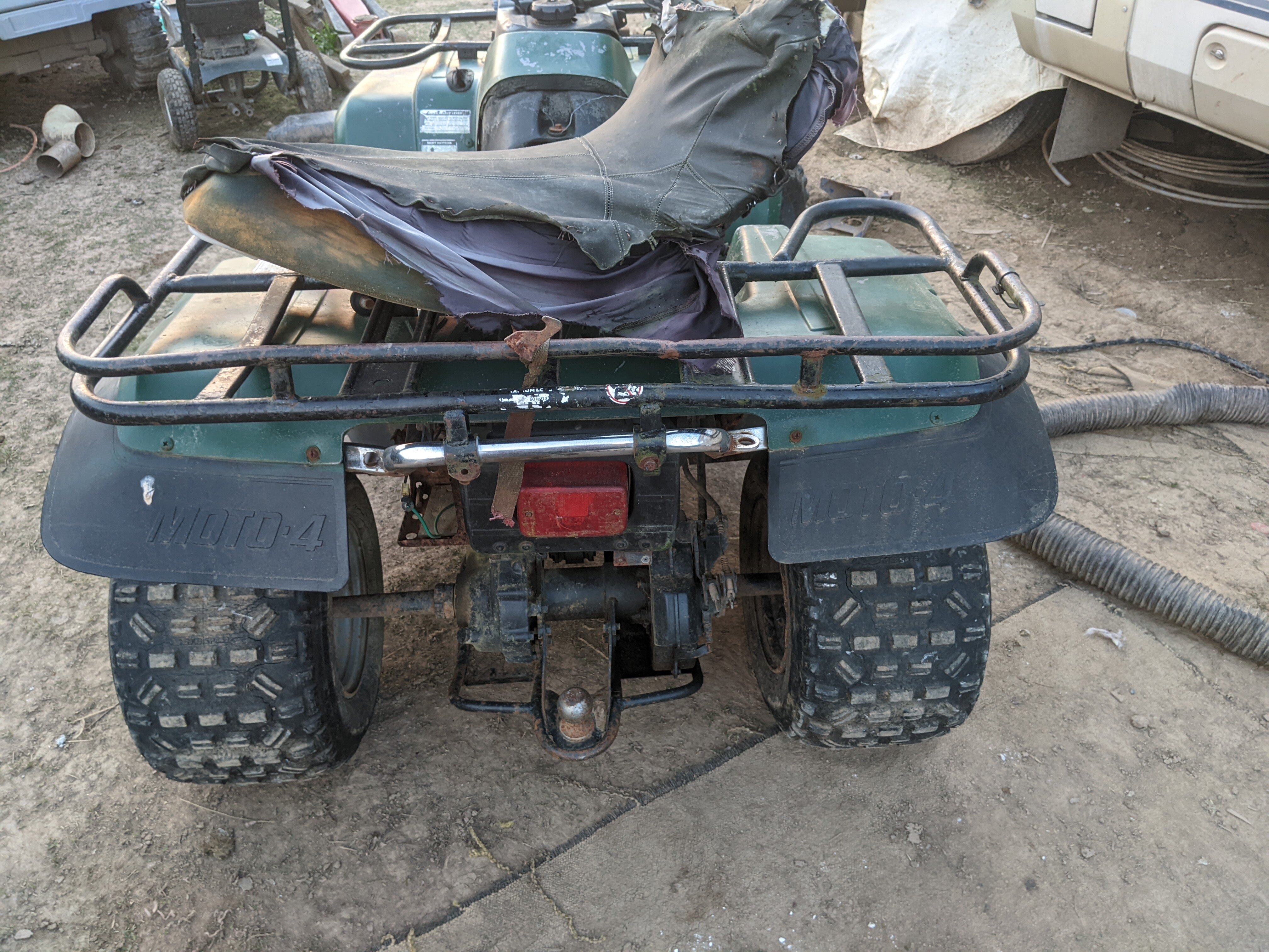
The flaps all say MOTO 4 embossed. Maybe hard to see in the photos. I am/was not sure if that was separate from a Big Bear, etc, or in addition to the model #. Has someone done a document explaining the differences? E.g. will a wiring harness for any 1990 YFM350 work on a MOTO 4? I'll ring a stealership next and try to get the harness part # out of the guy.
-
VinDecoderz says it's a YFM350 (Moto4 350) trim YFM350ER Is that a Big Bear? Or a Moto 4? Or are they the same thing? I've google'd around for information, and was able to find a (czech board in english) that had a Yamaha service manual for the YFM350X series, LIT-11616-YM-37. The 'Warrior' type. I'm trying to get something more accurate. I'm not sure which manual I need. Pictures included in this post. I'm also looking to get a wiring harness for it.